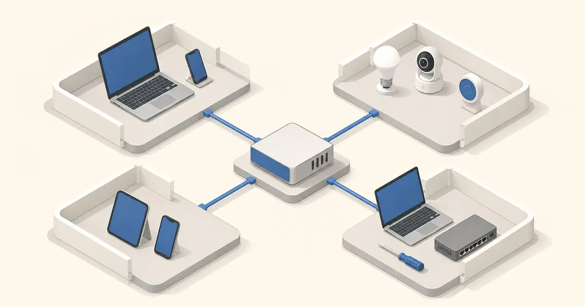
This opnsense vlan setup tutorial builds four routed security zones: trusted clients, IoT devices, guests, and network management. The result is one physical LAN link carrying four 802.1Q tags, with OPNsense routing between unique /24 networks and blocking inter-VLAN traffic unless a rule explicitly permits it.
The goal
VLANs separate Layer 2 broadcast domains; OPNsense supplies each gateway and controls routed traffic between them. Hosts in one VLAN still communicate directly, outside firewall control, as the OPNsense VLAN guide notes.
Segmentation holds only when three things are all true: the OPNsense sub-interfaces carry the right tags, the managed switch’s trunk and access ports match them, and the firewall rules on each VLAN interface actually block inter-VLAN traffic. A VLAN with no restricting firewall rule is a flat network with extra steps. That means a switch that supports 802.1Q tagging and an access point that either maps SSIDs to VLANs or accepts a tagged trunk; an unmanaged switch cannot enforce any of it.
This guide assumes a working WAN and LAN. From a fresh install, the OPNsense initial setup guide gets you to that point first. Keep the existing LAN while building this. Test each VLAN on a spare access port before moving the admin workstation, and keep console access available.
Topology
Example hardware: OPNsense router, USW-Pro-24-PoE, and U6-Enterprise.
ONT -> OPNsense igc0 (WAN) -> OPNsense igc1 -> USW-Pro-24-PoE port 24 -> U6-Enterprise on port 1
igc1to switch port24: trunk, tagged VLANs10,20,30,99, no native VLAN.- Switch port
1to U6-Enterprise: trunk, native/PVID99for AP management; tagged10,20,30for SSIDs. - Switch port
2: access port, untagged VLAN10, PVID10. - Switch port
3: access port, untagged VLAN20, PVID20. - SSIDs:
Home-> VLAN10;Things-> VLAN20;Guest-> VLAN30.
An access port applies its PVID to untagged ingress frames and removes the tag on egress. The OPNsense trunk should carry tags only; mixing native and tagged VLANs there can leak DHCP, RA, or CARP traffic on some switches, according to the official guidance.
Two switch-side mistakes account for most broken VLAN builds:
- Native VLAN mismatch. If the switch sends VLAN
1untagged on the trunk while OPNsense expects everything tagged, untagged management traffic leaks onto the wrong segment. Point the trunk’s native VLAN at an unused ID and never put trusted devices on VLAN1. - Untagged SSIDs. The AP uplink is also a trunk, so map each SSID to its VLAN on the AP. A
GuestSSID that is not actually tagged onto VLAN30lands on the native VLAN and bypasses every rule below. For UniFi access points, UniFi VLAN segmentation for IoT, guest, and trusted covers the SSID-to-VLAN mapping in the Network Application.
Verify at the switch before touching OPNsense: most managed switches show a VLAN membership table. Confirm the OPNsense port is tagged for all four IDs and that each access port is untagged on exactly one.
VLAN plan
These are example private networks; all sit inside the address space defined by RFC 1918, Address Allocation for Private Internets.
| VLAN ID | Name | CIDR | DHCP range | Gateway | Inter-VLAN policy |
|---|---|---|---|---|---|
| 10 | TRUST | 192.168.10.0/24 | 192.168.10.100-192.168.10.199 | 192.168.10.1 | Deny by default; admin host may manage VLAN 99 and initiate to IoT |
| 20 | IOT | 192.168.20.0/24 | 192.168.20.100-192.168.20.239 | 192.168.20.1 | Deny local networks; optional Home Assistant exception |
| 30 | GUEST | 192.168.30.0/24 | 192.168.30.100-192.168.30.239 | 192.168.30.1 | Internet and firewall DNS only |
| 99 | MGMT | 192.168.99.0/24 | 192.168.99.100-192.168.99.149 | 192.168.99.1 | No initiation into client VLANs; admin host allowed in |
Create and assign the VLANs
In Interfaces > Devices > VLAN, add tags 10, 20, 30, and 99, all with parent igc1. Use descriptions such as igc1_vlan20_IOT. Each tag must match exactly what the switch sends on the trunk. Then open Interfaces > Assignments, assign each device, and rename the interfaces TRUST, IOT, GUEST, and MGMT; the default OPT1 to OPT4 names make every rule harder to read.
Enable each interface, choose Static IPv4, and assign its /24 gateway address. Do not set an upstream gateway. Leave igc1 unassigned, with no address of its own, since the parent carries only tagged frames, and configure no native VLAN on the switch trunk, matching the documented tagged-parent design.
Keep MTU 1500; a VLAN tag is not a reason to enable jumbo frames. Change it only end to end.
Configure DHCP
Use Services > Dnsmasq DNS & DHCP. Enable Dnsmasq, select all four VLANs, set Listen Port to 0 so Unbound keeps TCP/UDP 53, and enable DHCP register firewall rules. Add the four ranges above, keeping each .1 gateway address outside its pool. Dnsmasq advertises the interface address as router and DNS server, per the OPNsense guide. A VLAN with no scope hands out nothing, so a client that never gets a lease is a DHCP or tagging problem before it is a firewall problem.
Do not run Dnsmasq, Kea, and legacy ISC DHCP on the same interfaces. If Kea is already authoritative, keep it and create the same four subnets under Services > KEA DHCP > KEA DHCPv4 instead of migrating mid-change.
For IPv6, give each VLAN a delegated /64, enable RA deliberately, and duplicate the policy below for IPv6. IPv4 rules do not filter SLAAC traffic.
Firewall rules
Create aliases LOCAL_NETS for the four CIDRs, ADMIN_HOST for 192.168.10.10/32, and HOME_ASSISTANT for 192.168.10.20/32. LOCAL_NETS can instead hold the full RFC 1918 set, 10.0.0.0/8, 172.16.0.0/12, and 192.168.0.0/16, so a fifth VLAN is covered the day it is created. Do not block only 192.168.0.0/16 and call it done: a VLAN or LAN living in 10.x or 172.16-31.x passes straight through, which is the single most common reason “my VLAN isolation isn’t working”. The rule and alias recipe generator emits the RFC 1918 alias and the ordered isolation rules ready to paste.
The firewall rules belong where traffic enters. OPNsense normally evaluates quick rules first-match, with floating and group rules before interface rules; see the processing order. Default deny is per interface: anything not explicitly passed is dropped, but only inbound on the interface that owns the rule set. Rules are not shared, so each VLAN needs its own copy of the rows marked “each VLAN”.
Apply these in order:
| Order | Interface | Source | Destination | Port | Action |
|---|---|---|---|---|---|
| 1 | each VLAN | its VLAN net | This Firewall | TCP/UDP 53 | Pass |
| 2 | TRUST | ADMIN_HOST | MGMT net | TCP 22,443 | Pass |
| 3 | TRUST | TRUST net | IOT net | any | Pass |
| 4 | IOT | IOT net | HOME_ASSISTANT | TCP 8123 | Pass, only if required |
| 5 | each VLAN | its VLAN net | any | TCP/UDP 53 | Block external DNS |
| 6 | each VLAN | its VLAN net | LOCAL_NETS | any | Block and log |
| 7 | each VLAN | its VLAN net | any | any | Pass to internet |
Dnsmasq’s automatic rule permits client UDP 68 to server UDP 67, as assigned by RFC 2131. DNS and host exceptions must precede their blocks. A broad pass above order 5 shadows the blocks. After tightening rules, clear affected states under Firewall > Diagnostics > Sessions.
Row 1 exists because row 6 would otherwise block DNS to the firewall itself. Extend it to TCP 853 if clients use DNS over TLS to Unbound, and add UDP 123 to This Firewall if a VLAN takes NTP from OPNsense. Do not add a pass to TCP 80,443 on This Firewall from IOT or GUEST; nothing in those zones needs the GUI.
Rule 7 is pragmatic for IoT. Replace it with logged vendor-specific allows if required. UPnP stays off, and blocking 53 does not stop DNS over HTTPS on TCP 443.
Check Firewall > NAT > Outbound: Automatic or Hybrid mode should include the new networks; Manual mode needs explicit WAN source-NAT rules for them. The OPNsense NAT manual explains the modes.
DNS and discovery
Leave Unbound on TCP/UDP 53. In Services > Unbound DNS > Access Lists, verify all four CIDRs have Allow entries; assigned interfaces normally create them, per the Unbound documentation. Use source-net Blocklist policies: normal resolution for TRUST, logged vendor-domain allow-lists for IOT, and no internal exceptions for GUEST. OPNsense DNS blocklists with Unbound covers the policy scoping and the cron task the lists need.
Bonjour discovery uses mDNS on 224.0.0.251:5353 or [ff02::fb]:5353, as specified by RFC 6762, Multicast DNS. If Home and Things must discover each other, install os-mdns-repeater and select only TRUST and IOT, following the OPNsense mDNS proxy guide. Reflection exposes discovery records; it does not open the discovered service ports. Keep GUEST and MGMT out.
IGMP snooping is an L2 multicast optimization, not an mDNS reflector. Enable it only with a working querier and verify discovery afterward. RFC 4541 says traffic in 224.0.0.0/24 should be forwarded on all ports, but switch implementations vary.
Things to test before you call it done
Run these from a client on each VLAN, substituting that VLAN’s gateway:
ping -c 3 192.168.20.1
dig @192.168.20.1 example.com A +short
dig @1.1.1.1 example.com A +time=2 +tries=1  # should time out
mtr -rwzc 20 1.1.1.1
If the first ping, to the client’s own gateway, fails, the fault is switch tagging or the PVID rather than a firewall rule; go back to the membership table before editing rules. If the gateway answers but the isolation tests below pass traffic, the fault is rule order.
Put an iperf3 server at 192.168.10.50, then test isolation from GUEST or IOT:
iperf3 -s
iperf3 -c 192.168.10.50 -p 5201             # should fail
Verify tags from the OPNsense shell with tcpdump -eni igc1 'vlan 20'. Test discovery with dns-sd -B _airplay._tcp local. on macOS or avahi-browse -art on Linux. Finally, inspect live firewall logs: the isolation tests should hit the logged LOCAL_NETS block, not disappear because the SSID landed on the wrong PVID.
When VLAN segmentation is the wrong tool
VLANs are Layer 2 isolation enforced by the firewall at Layer 3. They are excellent for “IoT cannot reach the NAS”, but they are not a substitute for host hardening, and they do nothing about a compromised device on the same VLAN. A VLAN boundary decides what may cross it; it says nothing about whether the traffic you allow is malicious, which is the gap an inline Suricata IDS/IPS fills. Isolating two trusted hosts from each other is a job for host firewalls or separate physical networks. And with a handful of devices and an unmanaged switch, the operational cost of VLANs can exceed the benefit: a single well-firewalled LAN plus a guest SSID may be enough. Add VLANs when untrusted device classes, such as IoT, guests, and cameras, genuinely need to share infrastructure.
VLANs contain traffic; they do not patch an abandoned camera. Track advisories through vendors and broader reporting such as Tech Sentinel.
Related across the network
- OPNsense vs pfSense in 2026: Honest, Side-by-Side Comparison — firewallcompare.com
- UniFi VLAN Setup Guide: Segment Your Network the Right Way — unifiguide.com
- Docker Macvlan in Compose: Give Containers a LAN IP — dockerhomelab.com


